Skip to main content
Commercial audio systems for Miami businesses.
© 2026 SoundMate. All rights reserved.
Audio System Electronics: Balanced Audio, Ground Loops, and Troubleshooting
Audio System Electronics: Balanced Audio, Ground Loops, and Troubleshooting Audio System Electronics: Balanced Audio, Ground Loops, and Troubleshooting
Electronics matter in audio systems. Here's how they work.
You hear problems: hum, pops, clicks, weird phasing. Here's what causes them.
Building on physics:
This post builds on the physics foundation. It uses impedance concepts, power calculations, and signal flow principles.
What this post covers:
Balanced vs unbalanced audio, ground loops, impedance, signal integrity, and real-world problems and solutions.
Why it matters:
Understanding electronics helps you understand problems. You know what to fix and how to prevent issues.
This knowledge applies to every installation.
Real-world approach:
This post shows problems first, then explains causes, then shows solutions, then shows prevention.
You learn by seeing real examples.
Electronics overview Balanced vs Unbalanced Audio
Balanced and unbalanced are different. Here's how.
Unbalanced Audio
What: Two wires: signal and ground.
One wire carries the signal
One wire is ground
Simple design
Fine for short cables
Picks up noise easily
Not suitable for long runs
Susceptible to interference
Used for short connections only.
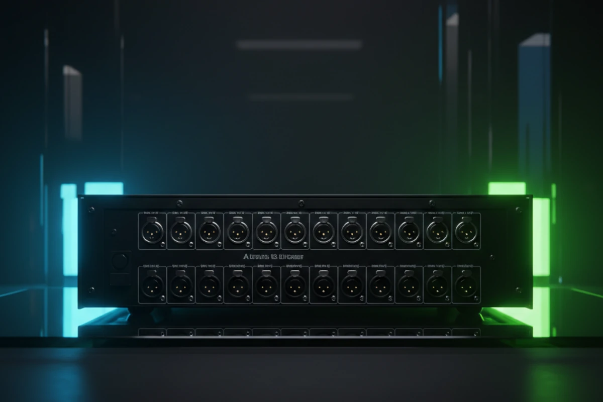
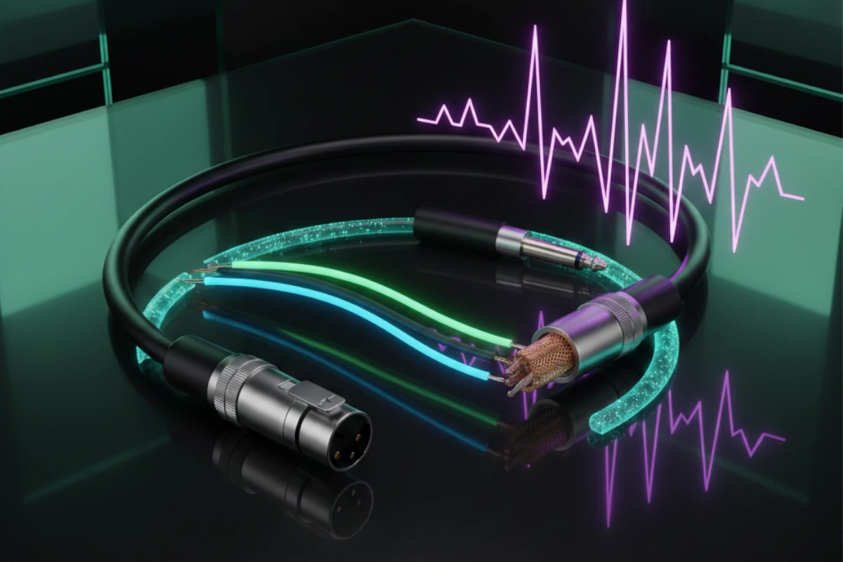
What: Three wires: two signals (inverted) and one ground.
Two wires carry signal (inverted)
One wire is ground
Noise cancels at receiver
Works for long cables
Cancels noise
Works over distance
Professional standard
Less interference
Used in professional installations.
Noise affects both signal wires equally. Receiver inverts one signal. Noise cancels. Clean signal remains.
This principle applies in professional installations.
Common Mode Rejection Ratio (CMRR)
What: How well balanced audio rejects noise.
Measured in: Decibels (dB). Higher is better.
Noise affects both signal wires equally. Differential amplifier subtracts signals. Noise cancels. Signal remains.
Good equipment: 60-80 dB CMRR
Excellent equipment: 80-100+ dB CMRR
Higher CMRR = better noise rejection. Cleaner sound. Professional quality.
Use equipment with high CMRR for best results.
Short cables (under 10 feet)
Consumer equipment
Simple connections
Long cables (over 10 feet)
Professional equipment
When noise is a problem
Choose based on your needs.
Signal Levels and Phantom Power Signal levels matter. Here's how they work.
Very weak signal
-60 to -40 dBu
Needs preamplifier
From microphones
Stronger signal
Consumer: -10 dBV
Professional: +4 dBu
From mixers, players, interfaces
Very strong signal
20-100 volts
High power
To speakers
Mismatched levels cause problems. Too weak = no signal. Too strong = distortion. Must match levels correctly.
Ensures: Proper level matching in all installations.
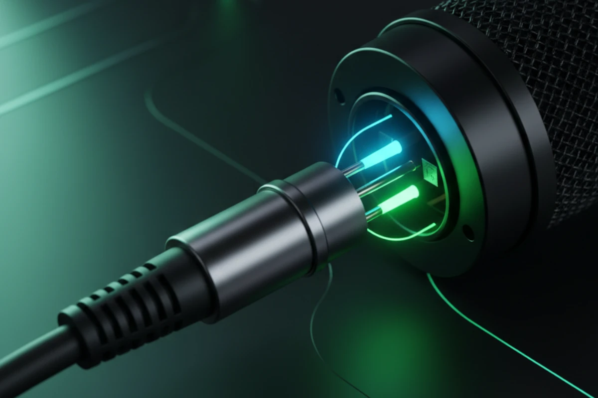
What: 48 volts DC sent through XLR cable. Powers condenser microphones.
Voltage on pins 2 and 3. Pin 1 is ground. Microphone uses power. Signal travels on same wires.
Condenser microphones (most need phantom power)
Some active DI boxes
Some ribbon microphones (check specifications)
Safe for dynamic microphones (they ignore it)
Safe for most equipment
Check equipment specifications first
Use phantom power for condenser microphones.
What: Setting levels at each stage. Prevents clipping. Prevents noise.
Set input level. Set processing level. Set output level. Each stage set correctly.
Too low = noise floor rises. Too high = clipping and distortion. Proper gain staging = clean sound.
Use proper gain staging in every installation.
Real-World Problem: Hum - Ground Loops You hear a constant hum. Here's why.
Constant low-frequency hum
60 Hz (or 50 Hz in some countries)
Gets louder with volume
Never goes away
Restaurant installs new audio system. Everything works. But constant hum in speakers. Can't fix it. Frustrating.
What happens when best practices aren't followed:
Multiple ground paths. Equipment grounded in different places. Current flows between grounds. Creates hum.
Multiple paths to ground. Current flows between them. Creates voltage difference. Causes hum.
Equipment A is grounded to outlet 1, and equipment B is grounded to outlet 2. When a cable connects them, a ground loop is created.
Ground loops are common. They cause most hum problems. Understanding them helps you fix them.
This problem occurs often. Here's how to fix it.
Solution 1: Single ground point
Connect all equipment to one ground to eliminate multiple paths.
This is applied in every installation.
Solution 2: Ground lift (careful)
Lift the ground on one piece of equipment to break the loop. Use only when safe.
Used only when necessary. Safety first.
Solution 3: Isolation transformer
Isolates equipment electrically, breaks the ground loop, and keeps the signal clean.
Used for difficult cases.
Plan grounding from start
Use single ground point
Check equipment grounding
Test before finalizing
Applied in every installation.
Prevention saves time, money, and frustration.
Ensures: Proper grounding in all installations.
Real-World Problem: Pops and Clicks - Defective Connectors You hear pops and clicks. Here's why.
Random pops
Clicks
Dropouts (sound cuts out)
Intermittent problems
Studio has intermittent audio. Pops during recording. Clicks when adjusting volume. Can't find the problem.
What happens when connectors aren't maintained:
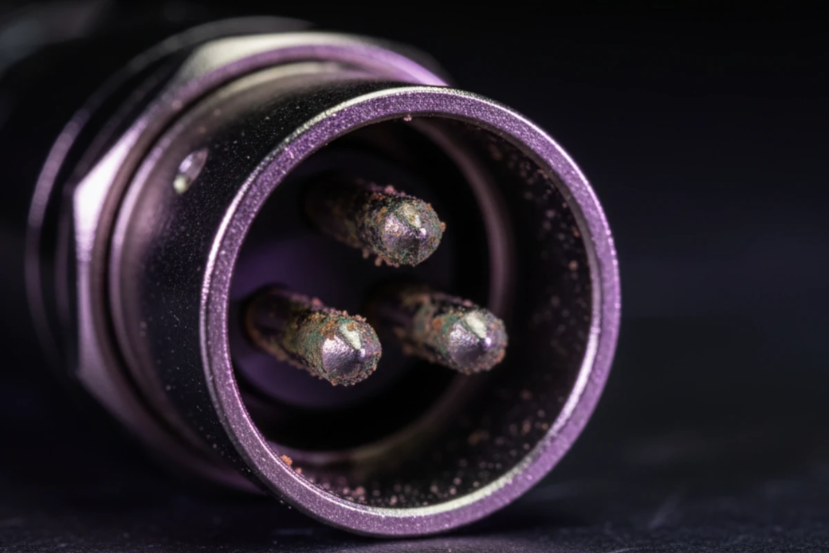
Dirty connectors. Loose connections. Worn ports. Corrosion. All cause problems.
The Cause: Defective Connectors or Ports
What causes pops and clicks?
Dust and dirt build up
Creates poor contact
Causes intermittent connection
Results in pops and clicks
Connector not seated properly
Movement breaks contact
Causes dropouts
Results in clicks
Repeated use wears contacts
Loose fit
Poor connection
Causes problems
Moisture causes corrosion
Poor electrical contact
Intermittent problems
Results in pops
These problems occur often. Here's how to fix them.
Solution 1: Clean connectors
Clean with contact cleaner to remove dirt and corrosion and restore good contact.
Performed regularly in maintenance.
Solution 2: Reseat connections
Unplug and replug to ensure proper seating, and check for damage.
Performed first when troubleshooting.
Solution 3: Replace damaged connectors
If worn or damaged, replace. Use quality connectors. Ensure proper fit.
Use quality replacements only.
Solution 4: Replace worn ports
If port is worn, repair or replace equipment. Restore proper connection.
Keep connectors clean
Check connections regularly
Use quality connectors
Protect from moisture
Handle carefully
Applied in every installation.
Prevention saves problems. Saves money. Saves downtime.
Ensures: Proper connector maintenance in all systems.
Real-World Problem: Comb Filtering - Mic/Speaker Placement You hear weird phasing. Thin sound. Here's why.
Weird phasing
Thin sound
Some frequencies missing
Unnatural sound
Live venue has two mics on stage. Sound is thin. Some frequencies cancel. Can't fix with EQ.
What happens when placement isn't considered:
Multiple sound sources. Different distances. Waves arrive at different times. Phase cancellation. Comb filtering.
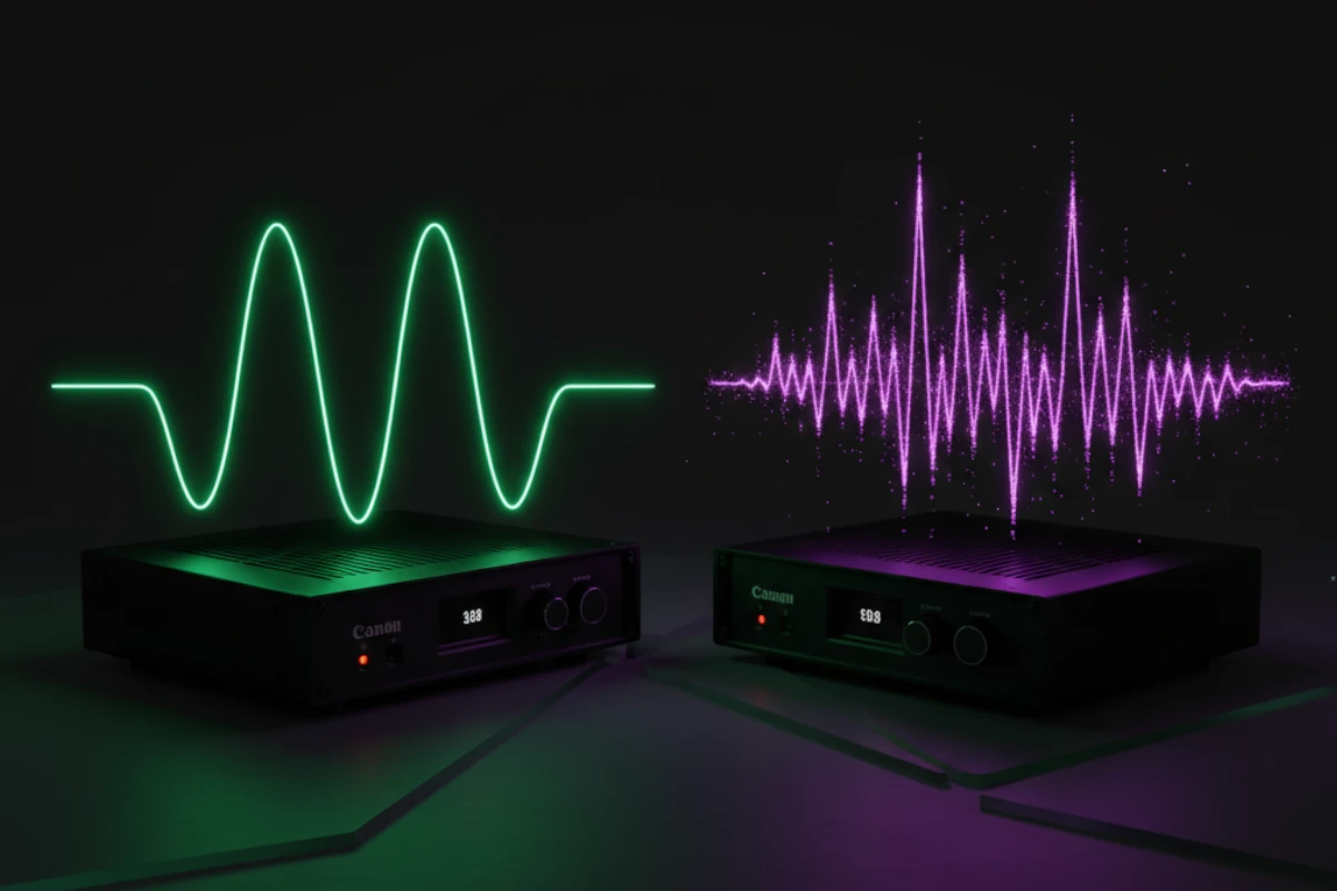
The Cause: Comb Filtering
Multiple sound sources. Different distances. Waves interfere. Some frequencies cancel. Some frequencies add. Creates comb pattern.
Frequency response looks like comb teeth. Peaks and nulls. Alternating pattern. Visual looks like a comb.
Two mics pick up same source
Different distances
Waves arrive at different times
Phase cancellation occurs
Multiple speakers play same signal
Different distances to listener
Waves arrive at different times
Phase cancellation occurs
Comb filtering ruins sound. Can't fix with EQ. Must fix with placement.
This problem occurs often. Here's how to fix it.
Solution 1: 3-to-1 rule (microphones)
Distance between mics should be 3x distance from source to nearest mic. Prevents phase problems.
Use this rule in all installations.
Solution 2: Proper speaker spacing
Space speakers correctly to avoid overlap zones and prevent phase cancellation.
Solution 3: Time alignment
Align speakers electronically so they have the same arrival time, which prevents phase problems.
Use DSP for time alignment.
Solution 4: Remove redundant sources
Use one mic instead of two. Use one speaker instead of multiple. Eliminates problem.
Plan placement from start
Follow 3-to-1 rule for mics
Space speakers correctly
Test for phase problems
Use time alignment when needed
Applied in every installation.
Prevention saves problems. Saves money. Saves sound quality.
Ensures: Proper placement in all installations.
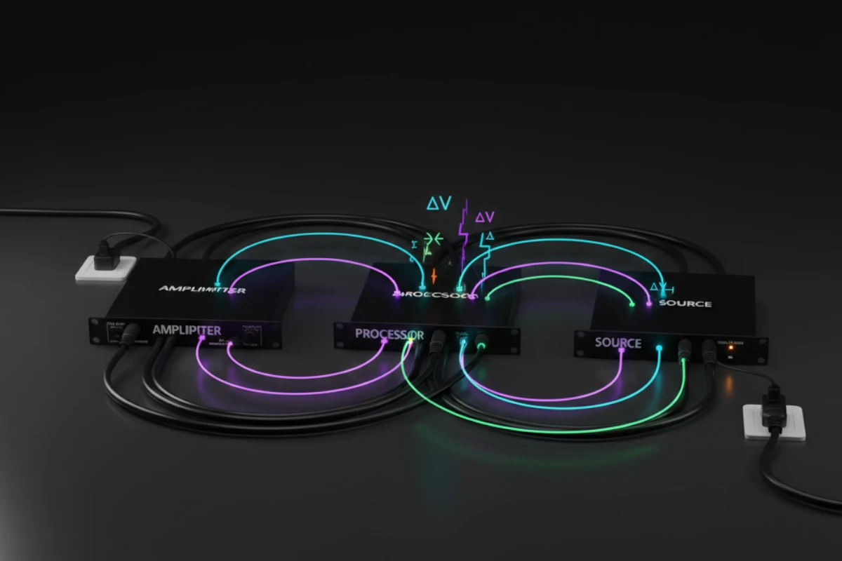
Ground Loops - Comprehensive Technical Explanation Ground loops explained technically. Here's the deeper explanation.
Multiple paths to electrical ground. Current flows between them. Creates voltage difference. Induces hum in audio.
Equipment A grounded to outlet 1
Equipment B grounded to outlet 2
Cable shield connects them
Ground loop created
Different ground points have different potential. Current flows. Creates voltage on cable shield. Induces hum.
Voltage = Current × Resistance (V = IR)
Voltage difference creates current. Current flows through cable shield. Creates hum in audio.
Power lines run at 60 Hz (50 Hz in some countries). Ground loops pick up this frequency. Creates 60 Hz hum.
Understanding ground loops helps you prevent them. You know what causes hum. You know how to fix it.
This knowledge applies to every installation.
Scenario 1: Different outlets
Equipment on different circuits. Different grounds. Cable connects them. Ground loop.
Scenario 2: Cable TV/Internet
Coax cable brings ground. Different from electrical ground. Creates loop.
Scenario 3: Multiple buildings
Different buildings. Different grounds. Cable between them. Ground loop.
These scenarios occur often.
Breaks electrical connection
Keeps signal
Eliminates ground loop
Professional solution
Breaks ground on one end
Use carefully
Safety considerations
Not always safe
Reject common-mode noise
Reduce ground loop effects
Professional standard
Best solution
These solutions work when applied correctly.
All equipment connects to one ground point. Like star shape. Prevents ground loops.
Ground bus bar. All equipment connects to bus. Common in racks.
Use star grounding for best results.
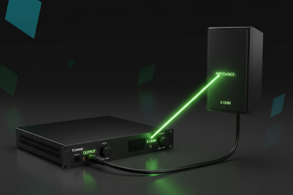
Impedance Matching Impedance matters. Here's why.
Resistance to electrical current. Measured in ohms (Ω). Affects power transfer.
Mismatched impedance causes problems. Power loss. Distortion. Equipment damage.
Ensures: Proper impedance matching.
4Ω: Low impedance. Harder to drive.
8Ω: Standard. Easy to drive.
16Ω: High impedance. Easiest to drive.
Amplifiers rated for specific impedance. Mismatch causes problems.
Match amplifiers to speakers.
Rule 1: Match amplifier to speaker
Amplifier rated for 8Ω. Use 8Ω speakers. Perfect match.
Rule 2: Multiple speakers
Parallel connection lowers impedance. Series connection raises impedance. Calculate carefully.
Calculate impedance for all configurations.
Input impedance should be 10× output impedance. General rule. Prevents loading. Ensures proper signal transfer.
Maximum power transfer
No distortion
Equipment protection
Best sound quality
Ensures: Proper matching in all installations.
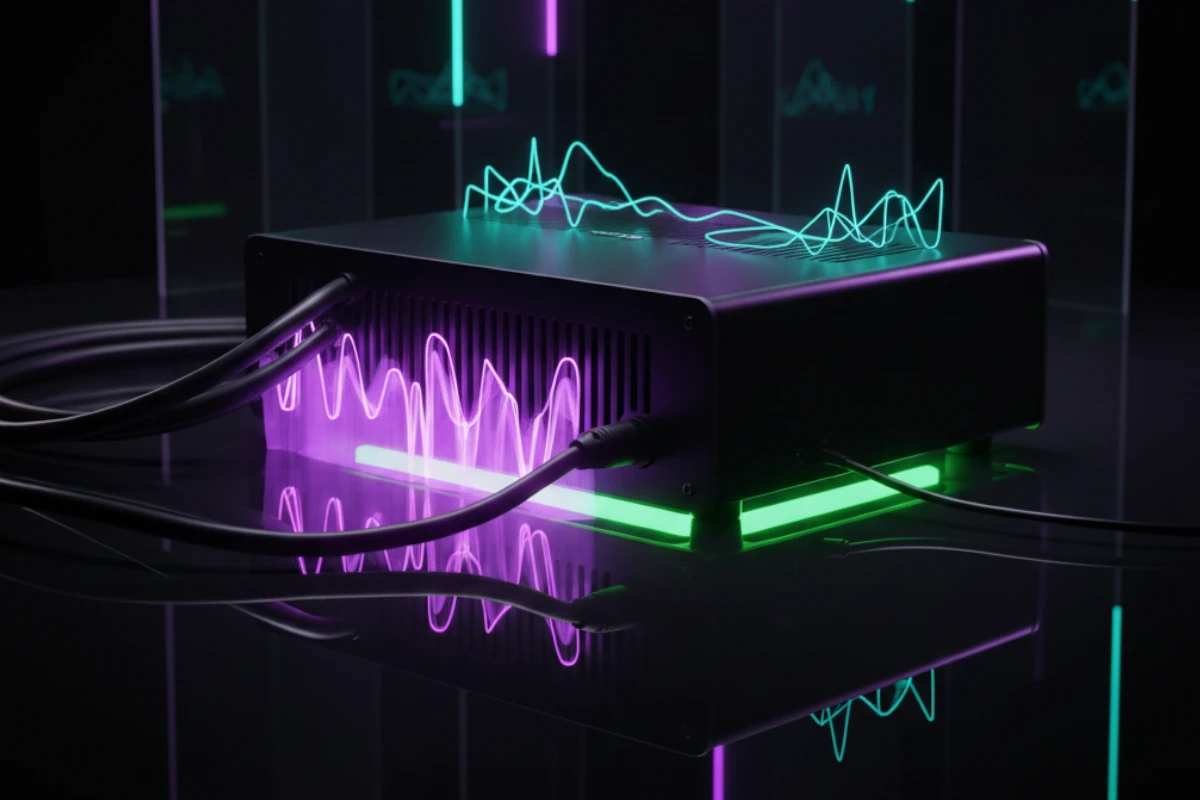
Signal Integrity Signal integrity matters. Here's how to maintain it.
What is signal integrity?
Clean signal from source to destination. No degradation. No interference. Original quality maintained.
Poor signal integrity ruins sound. Distortion. Noise. Loss of quality.
Ensures: Signal integrity in all installations.
Factors affecting signal integrity:
Good cables = better integrity
Poor cables = degradation
Shielding matters
Length matters
Use quality cables always.
Electromagnetic interference
Radio frequency interference
Power line interference
All degrade signal
Minimize interference in all installations.
Maintaining signal integrity:
Use balanced connections:
Reject common-mode noise
Better signal integrity
Professional standard
Good shielding
Proper construction
Right length
Quality connectors
Single ground point
No ground loops
Clean signal
Use all these techniques.
Good signal integrity means:
Clean sound
No distortion
No noise
Professional quality
Ensures: Signal integrity in every installation.
Noise Sources and Reduction Noise ruins sound. Here are sources and solutions.
Electromagnetic interference (EMI):
Power lines
Motors
Transformers
Fluorescent lights
Radio frequency interference (RFI):
Cell phones
WiFi
Radio transmitters
Wireless devices
Multiple ground paths
Voltage differences
60 Hz hum
Common problem
Identify noise sources in every installation.
Use balanced connections:
Reject common-mode noise
Cancel interference
Professional standard
Shielded cables
Shielded equipment
Proper grounding
Reduces interference
Keep audio cables away from power
Separate runs
Cross at 90 degrees
Minimize interference
Use all these techniques.
Cleaner sound
Better quality
Professional results
Happy customers
Ensures: Noise reduction in all installations.
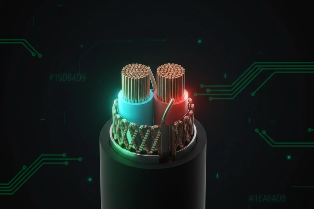
Shielding and Grounding Shielding and grounding protect signal. Here's how.
What: Metal shield around signal wires. Protects from interference.
Braided shield: Flexible. Good coverage.
Foil shield: Complete coverage. Less flexible.
Combination: Best of both.
Use quality shielded cables.
Shield intercepts interference. Routes to ground. Signal stays clean.
Good shielding means less noise. Better sound quality.
Ensures: Proper shielding in all cables.
What: Connection to earth. Safety and signal reference.
Protects equipment
Provides signal reference
Reduces noise
Prevents shocks
Ensures: Proper grounding in all installations.
All equipment to one ground
Prevents ground loops
Clean signal
Use single point grounding always.
Proper shielding and grounding mean:
Less noise
Better signal
Safer installation
Professional quality
Ensures: Proper shielding and grounding in every installation.
Conclusion - Best Practices Prevent Problems Best practices prevent problems. Use them consistently.
Balanced audio reduces noise (three wires cancel interference, CMRR matters)
Phantom power needed for condenser microphones (48V through XLR)
Signal levels must match (mic, line, speaker levels different)
Gain staging prevents clipping and noise (set levels at each stage)
Ground loops cause hum (single ground point prevents them, Ohm's law explains why)
Defective connectors cause pops (clean and maintain them)
Comb filtering ruins sound (proper placement prevents it, frequency response looks like comb)
Impedance matching matters (match amplifiers to speakers, input should be 10× output)
Signal integrity is critical (quality cables and proper grounding)
Noise reduction improves quality (shielding and separation)
Understanding electronics helps you understand problems
Understanding electronics helps you:
Identify problems quickly
Fix issues correctly
Prevent problems from happening
Make informed decisions
This knowledge applies to every installation.
This post showed problems first. Then explained causes. Then showed solutions. Then showed prevention.
You learned: By seeing real examples.
Learn about connectors (next post covers all types, including XLR used for balanced audio)
Review physics foundation (impedance, power, signal flow from previous post)
Explore more topics (building on this foundation)
Understanding these concepts helps you make informed decisions.
Continue Learning Next post: Complete Audio Connector Guide (all types including Phoenix, Dante, and conversion - balanced audio from this post uses XLR connectors)
Previous post: Audio Systems Physics (scientific foundation - impedance, power, and signal flow concepts)